Bidirectional motor controller with Arduino
The Arduino boards, with lots of analog and digital inputs and outputs, allow us to control electronic devices from a computer through an USB interface with a very simple programming using a language similar to C. There are lots of prefabricated modules for controlling motors, relays and all kinds of sensors, but, if you like electronics, like me, you can design and connect your own analog or digital circuits.
In this article I will show how to build a simple circuit to control a DC motor and the way to control the rotation in one direction or another using an Arduino board and a simple program written in CSharp.
In this link you can download the project BidiMotorArduino with the source code of the program, written with Visual Studio 2013.
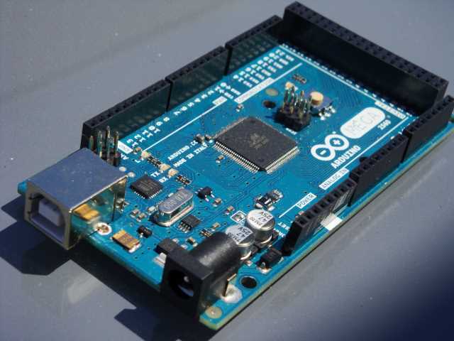
The first thing you need is an Arduino board. The price of these boards is quite affordable, so it is best that you acquire the most complete you can get. I, for example, have the Arduino MEGA with a lot of inputs and outputs.

The motor I will use is an old recycled electric screwdriver. It works with about 3 volts and has a great power, which allows us to move heavy loads.

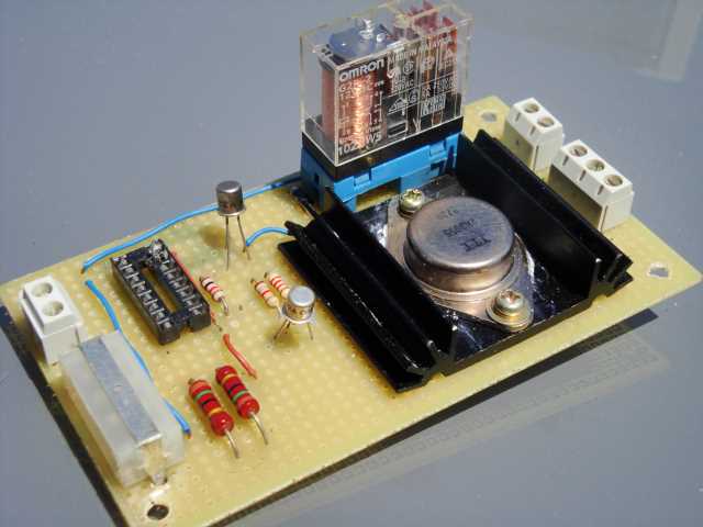
To control the motor, I have built a simple board consisting of a two-circuit relay to change direction of motor rotation, controlled by a transistor, and another pair of transistors that turn on and off the motor.

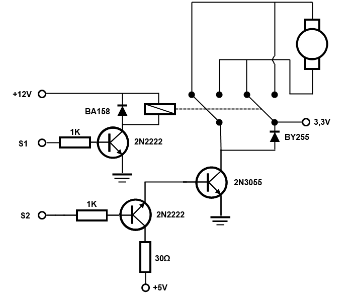
This is the circuit schema:

The relay, which switches the two circuits is controlled by a 2N2222 NPN transistor, which is activated or deactivated by one of the digital outputs from the Arduino board. It operates on 12 volts and the BA158 diode protects the transistor against the return currents that can occur when the coil is depolarized.
To turn on or off the motor, I use a 2N3055 transistor. This transistor supports a maximum current of 4 amps, allowing us to control powerful engines. The BY255 diode protects the transistor as in the previous case.
As the base current to activate the transistor 2N3055 can be high, instead of connecting it directly to one of the digital outputs from the Arduino board, I use the 5 volt output of the power supply, controlled by another transistor 2N2222, which needs only a few milliamperes from the Arduino output.
As power supply, I used one from a PC, which offers all the voltages required for this circuit and for the Arduino board. (The Arduino can be powered simply from the USB connection, but if you connect it to an external power supply, you can increase the maximum power of their output signals).
If you want to see the complete assembly where I used this circuit, you can follow this link where I explain how to build a robotic airsoft turret.
The program for the Arduino controller is very simple. In my case, I use the pin 22 to control the relay, and the pin 24 to turn on or off the motor:
void setup() {
    pinMode(22, OUTPUT);
    digitalWrite(22, LOW);
    pinMode(24,OUTPUT);
    digitalWrite(24, LOW);
    Serial.begin(9600);
}

void loop() {
    if(Serial.available() > 0) {
        int val = Serial.read();
        if (val & 1) {  // Change motor direction
            digitalWrite(22, HIGH);
        }
        else {
            digitalWrite(22, LOW);
        }
        if (val & 2) {  // Move the motor
            digitalWrite(24, HIGH);
        }
        else {    // Stop the motor
          digitalWrite(24, LOW);
        }
    }
}
And, from the C# program, we just have to write a byte to the serial port with bits 0 and 1 set or reset:
SerialPort p = new SerialPort(txtCOM.Text);
p.BaudRate = 9600;
p.Open();
byte[] val = new byte[1] { 2 };
p.Write(val, 0, 1);
p.Close();
Finally, I leave a couple of books to get started in the Arduino world:


