Cellular automata, WinCA application I
Cellular automata are mathematical models used to study the evolution of complex dynamic systems by simulating the interactions over time of a large number of elements, called cells. In this series of articles I will present the WinCA application, with which you can build and run this type of objects.
In this link you can download the WinCA application executables, and in this other one you can download the source code of the WinCA solution, written in CSharp with Visual Studio 2015.
There are many other programs to build and study cellular automata. One of the best and most complete is DDLAB. Here you have the discrete dynamics lab website, where you can download the program and documentation.
Although cellular automata are typically represented using lines or grids of cells, really a cellular automaton is a network of interconnected cells that can have any geometry, even irregular ones, with a different number of connections per cell.
The cells of a cellular automaton may be in a state of a certain set, usually finite, of them. These states are represented by coloring the cell with the color assigned to the state. For each of the states, there are a series of rules that establish under what conditions the cell change from that state to another one.
For each cell a neighborhood is defined, consisting of another series of cells with which it is connected. Thus, passing from one state to another takes into account both the state of the cell and the state of its neighbors, checking the conditions established by the rules mentioned above.
Depending on the type of evolution of the automaton, they can be classified into four types:
- Class I: The system always evolves to a fixed state and remains in it, no matter of the starting configuration.
- Class II: The system evolves to a periodic dynamics, passing over and over again by the same set of states.
- Class III: The system evolves to a chaotic dynamics, presenting an aspect of great disorder.
- Class IV: Systems with complex dynamics. They are on the border between chaos and order. These are the rarest automata, and the most interesting to model the behavior of natural systems.
As an introduction to the WinCA program, I will show some examples of different types of automata.
One dimensional linear cellular automata
The simplest type of automata is formed with finite-length line of cells. Each cell has as neighbors the cell to the left and the cell to the right and there are only two possible states. In more complex versions you can set an arbitrary number of states and neighbor cells.
Usually, these systems are represented in a two-dimensional grid, so that we can see the evolution of the system over time. Each line represents the complete state of the automaton in one of the steps.
For this simple type of automaton, the rules are abbreviated using a number between 0 and 255 which is obtained from the complete set of possible states of three adjacent cells and their corresponding transition. For example, rule 22 is set as follows:
Current state:   111 110 101 100 011 010 001 000
Next state:       0   0   0   1   0   1   1   0
Where the next state represented is that of the central cell. We can see that this is equivalent to the following rules:
- A cell in state 1 goes to state 0 if it has one or two neighbors in state 1
- A cell in state 0 goes to state 1 if it has a single neighbor in state 1
The number 22 that names the rule is obtained by joining the final states of all combinations into a single binary number.
Let's look at an example of that rule by using the WinCA application. After running the program, use the Open option in the File menu and select the file type automata files (* .cauto). In the Examples subdirectory of the application you can find the file rule22.cauto:
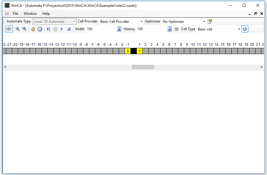
In the toolbar at the top you can select the type of automaton. In this case, since you have loaded a predefined automaton, the type cannot be changed. When you are designing the automaton, as you will see in later articles, you can change the type to make the states interact in different configurations of cells and dimensions.
The cell provider is the component that will supply the types of cells with which the automaton is built. By the moment there is only one type available, which is the basic cell provider.
The optimizer is a component that allows accelerating the execution of the automaton saving the known configurations to avoid having to evaluate the expressions of state change for each cell every time. It can be useful if these expressions are very complex or perform heavy calculations. Obviously, if random expressions are used, we will not be able to use an optimizer. In later articles we will see how to construct the expressions of change of state.
The last button on the top bar is used to display the state editor that corresponds to the automaton, which we will see in the next article in the series.
The next toolbar contains the automaton controls. From left to right they are the following:
- Show / Hide Neighborhood Editor: With this button you can control the display of the editor that appears below the toolbar, which I will comment on later.
- Zoom buttons: Used to decrease or increase the size of the automaton image.
- Speed control buttons: Used to slow down or speed up the automaton when it is running in automatic mode.
- Run Button: The automaton automatically advances step by step.
- Pause button: With this button you can stop the automatic advance, without losing the position.
- Step-by-step button: To advance one step.
- Reset button: To return to the initial state of the automaton, the step 0.
The remaining controls are dependent on the automaton type. In the case of the linear automata are the following:
- Width editor: Where you can change the number of cells of the automaton, typing a new value and pressing the button located in the right side of the editor.
- History editor: Where you can configure the memory that you want to save from the past states of the automaton. This will allow you to see the execution as a grid of Width x History cells.
- Initialization button: This button will open a dialog box to set the initial state of the automaton.
- Cell type: To select the type of the automaton cells. Only the basic cell type is available by now.
- Definition of border type: With this button you can select if the automaton ends on the left and right edges or if the left edge continues in the right one in a circular way.
The initial state editor looks like that:
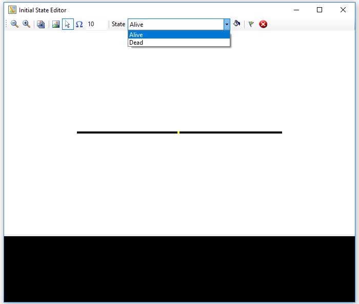
In the toolbar, from left to right there are the following controls:
- Zoom buttons: To decrease or increase the size of the automaton's initial image.
- Pattern selection button: With this button you can select a series of image files that will be used to create state patterns. These files will appear at the bottom (in black) of the dialog box.
- Pattern Mode button: When this option is selected, you can choose one of the patterns previously loaded at the bottom of the window (clicking on it with the mouse) and create on the automaton image a pattern of states determined by The selected image by clicking on it with the left mouse button. Pixels in the image that are not black will be converted into cells with the state selected in the dropdown.
- Cell Mode Button: When you left-click on one of the cells in the automaton, the state selected in the drop-down list will be assigned to it.
- Random state assignment button: This button will assign the selected state in the drop-down list to the number of cells indicated in the text box, randomly.
- State selection drop-down: To select the state to be assigned with the different options.
- Fill Button: When you press this button, all the cells in the automaton will be initialized with the state selected in the drop-down list.
- Save button: Once the automaton is initialized, this button allows you to save the changes.
- Cancel button: To discard all changes.
In the central part of the window you can see the initial state of the automaton as an image, and in the lower part, with black background, the state patterns that you have selected, if you did it.
Returning to the automaton form, below the toolbars is the neighborhood editor of the automaton. In the center, there is a black rectangle that represents the current cell. To mark another cell as a neighbor, you must click on it with the left mouse button, and its color will change to yellow. You can delete a neighbor by clicking on the cell with the right mouse button.
On the cell there is number that corresponds to that neighbor, that can be referenced using this index in the change of state expressions. All the cells of the automaton will be initialized with the neighborhood structure that is established this way.
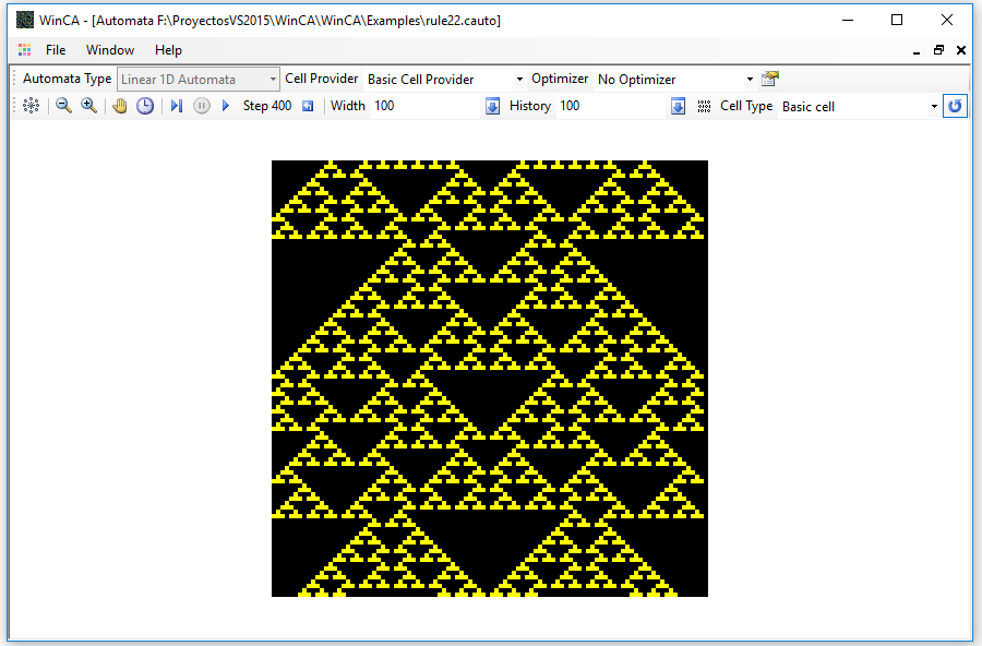
When running the automaton, you can see its evolution over time. This is an example in which we start from a single initial cell in active state in the center of the automaton, after a few steps:
Two dimensional cellular automata
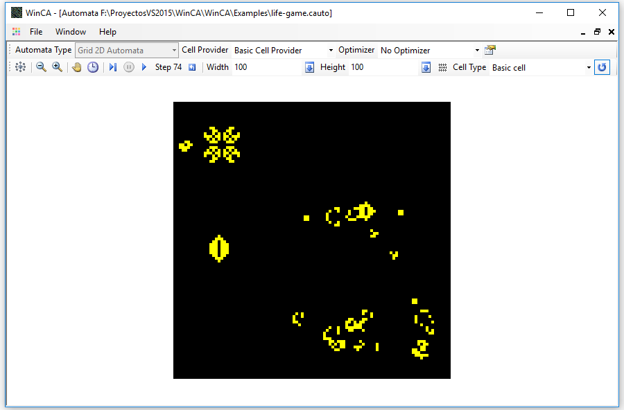
If we now open the file life-game.cauto we can see a two-dimensional automaton, the well-known Conway's game of life. This is a sample of the automaton initialized with some of the typical structures of the game:
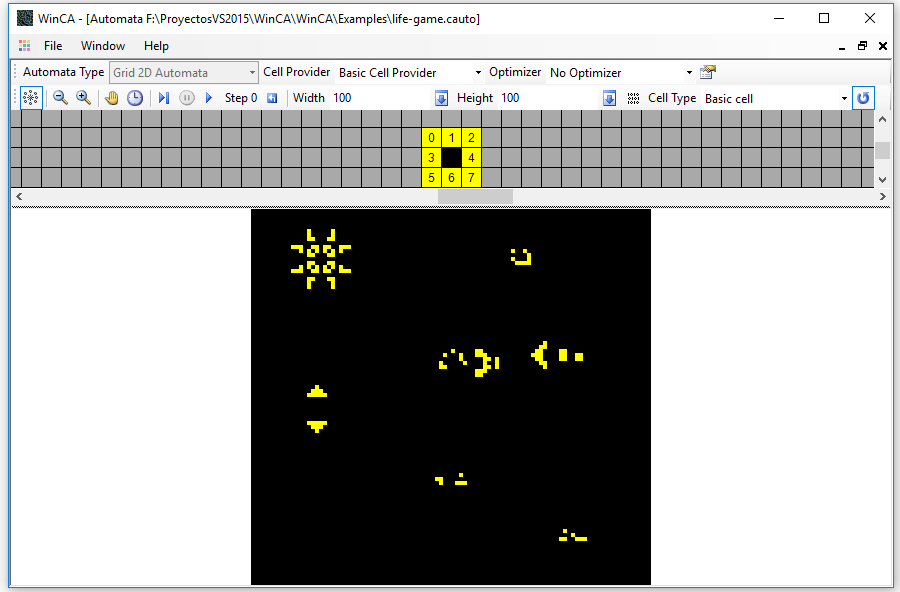
The only difference in the controls is that now there is a text box for the high of the grid replaces that of the history. You can also see that the neighborhood editor is different, allowing you to define neighbors in two dimensions.
Although in these automata it seems that the elements move around the available space, it must be taken into account that there is no movement of any kind at all. Each cell changes its state according to its neighbors, not their place. The movement is only apparent. This is the state of the automaton after a few steps:
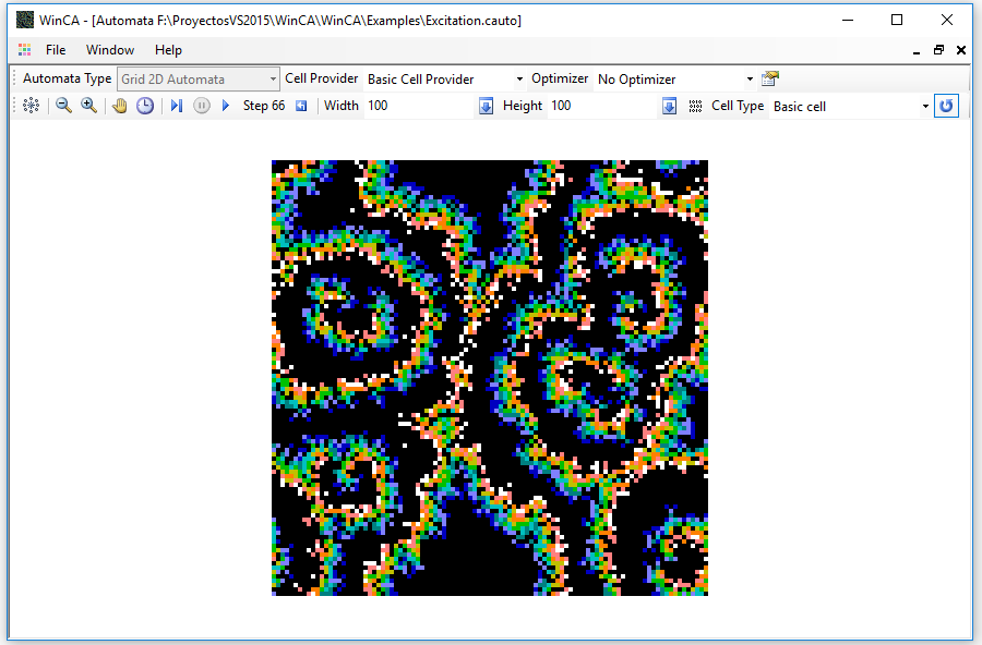
Finally, we can open the automaton Excitation.cauto to see the execution of an automaton with more than two states. It is an automaton with a random state change function that simulates a kind of excitation / relaxation state wave.
That's all for the moment. In the next article I will show how to use the WinCA application property and state editors.


