Training sparring robot II
This article is the second one on the Octopussy training sparring robot for self-defence and martial arts. Here, I will explain how to build the electronics of the invention. The task consists of little more than connecting a few wires, although a tin soldering iron would also be convenient to have at hand to finish the job better. Here is a link to the first article in this series, where I explain the assembly of the mechanical parts, and you can download the necessary software for the device to work.
You will need a junction box large enough to contain all the component boards. I have used one box of 20 x 25 x 10 cm:
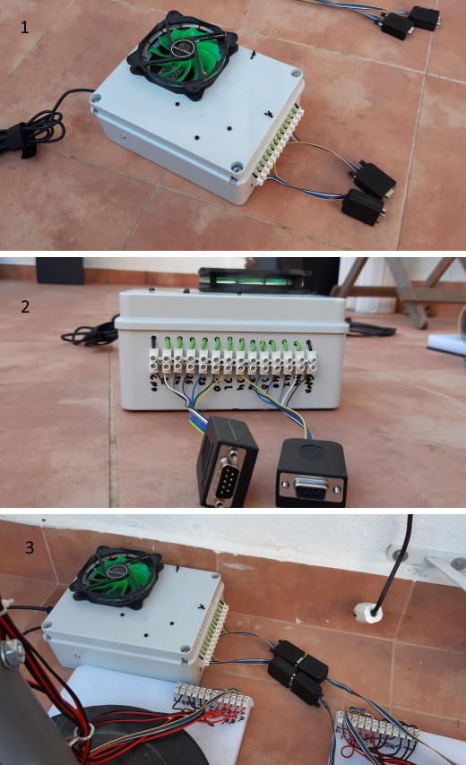
You can see in figure 1 the junction box, with the USB cable to connect the computer at the back, the connectors with the two side towers at the front, and a fan at the top to extract the heat, which is optional since the power source will not have too much work. Figure 2 shows the 14 terminal strip and two connectors. With the connector model I have chosen, it is unnecessary to solder any cables, for they contain a connection strip in which you can fasten them using a screwdriver. I have put a male and a female connector so as not to confuse them when connecting the robot's two side towers. If you use coloured cables, it will be easier not to make mistakes.
You can see at both ends of the box's connection strip the black ground cables, one for each tower, which come directly from the power supply. The green wires are for the 12 V of the motors. They come from 12 relays located inside the box that turn the motors on and off. The six cables on the left are for the right limbs tower, and the six ones on the right for the left limbs tower. Although it is very unclear, because of my awful handwriting, under each connection, I have written the Arduino board pin number corresponding to each cable. I have used the even pins 22 to 44, as we will see later.
You can see in figure 3 the box connected to the towers, which must also have a connector attached to its base connector strip. Use the same color code on both sides so as not to make mistakes. The inside of one of these connectors is like the one in this image:
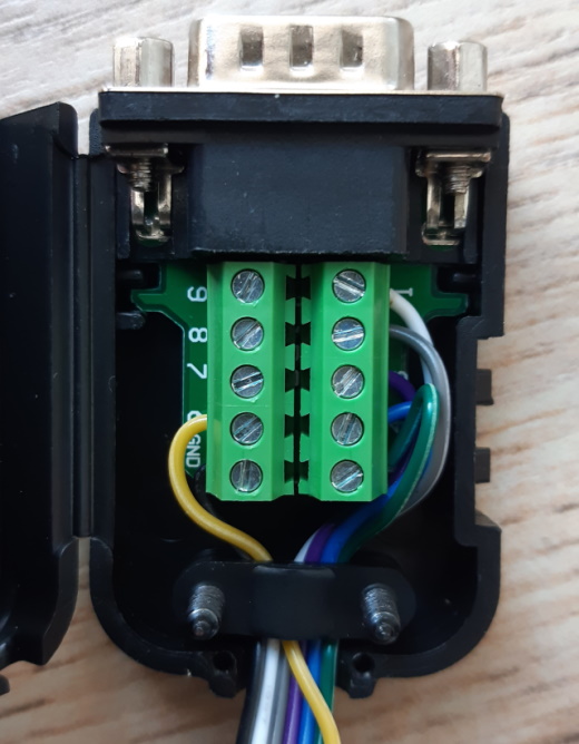
As you can see, each connector pin is numbered in the position where you have to connect the cable. There is also a GND pin, which is for the ground and corresponds to the connector's metal case. If you use coloured wires, you just have to connect the cable of the same color to the same number position on the two connectors connecting to each other. I have used pins 1 to 6, plus GND, so you need seven cables per connector.
The following image shows the inside of the junction box:
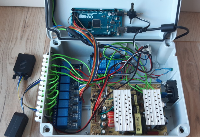
The Arduino Mega board, which connects the computer with the relays through a USB cable, is on the box's cover. The jack above the USB cable connects the Arduino board to the 12 V of the power supply.
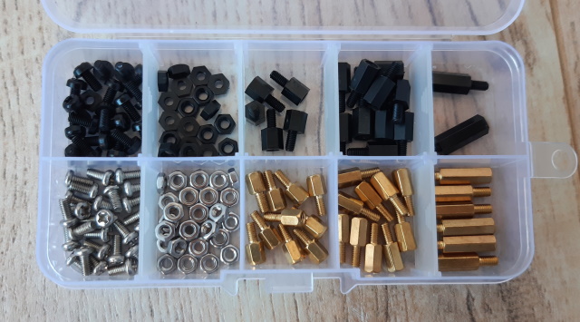
The relays that turn the motors on and off are the two blue boards at the bottom. There is an eight relay board and a four relay one. The larger board is a 500W PC power supply, which I have removed from its box. This type of power source provides many amps and is very cheap. All boards are attached to the junction box using spacers, like the ones shown in the following image:
You have to connect a pair of cables for the PC power supply to turn on, as indicated in this link. They are the cables used for the PC power button. You will also have to remove all the excess wires since you do not need most of them:
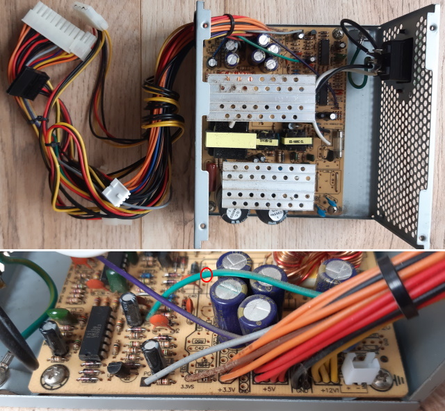
You can see the power supply with all its cables in the figure at the top. There is also a connector in the box for the power cable and a switch, which you can remove to put them in the junction box.
You can see all the cables from the source at the bottom image. We only need the 12 V cables, the yellow ones, and the ground black ones. You can cut all the other wires, taking care that they do not short circuit, or better yet, remove them using a tin soldering iron. In this case, you will also have to be careful to avoid short circuits. The blue wire separated from the others, marked with a red circle, is the one that you have to join with one of the black ground wires for the power supply to turn on. In the image where I show my assembly, you will see no yellow cables since I have reused a power source from which I had previously removed all the wires, but you will save work using the power source cables.
You will need a cable like the one in the image to connect the Arduino board to the relays:
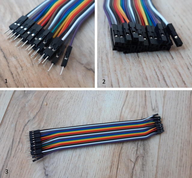
This cable has a male connector at one end to connect to the Arduino board and a female connector at the other end to connect to the relays, as you can see in figures 1 and 2. You will have to separate a ten-wire harness for the eight relay board: one for 5 V, another for ground, and 8 to activate the relays. You have to separate a six-wire harness in the same way for the four relay board.
You can see in more detail the Arduino board connections in the following image:
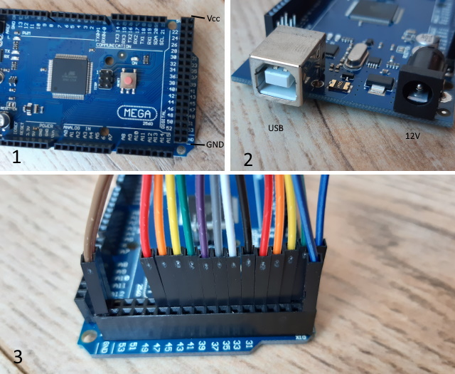
You can see in figure 1 the rear connector on the right. I have marked with Vcc the two pins at the top end corresponding to the 5 V supply for the relays and with GND the two pins at the bottom end to connect to the relays' GND. You can see in figure 2 the USB port to connect the board to the computer and the female jack for the 12 V and the ground from the power supply. You have to use a male DC jack of the appropriate size. You have to connect the ground to the outside of the jack and the 12 V to the inside. You can try with only the USB cable before using this 12 V jack. In this case, the Arduino board will take power from the computer through the USB port.
You can see in figure 3 the cables that go to the relays connected to the Arduino Mega's rear connector. Note that there are two cables at the connector's left and right ends instead of just one. These are the power cables for the relay boards; the blue ones are connected to the Vcc socket and the brown ones to the GND socket. The rest of the wires are connected to the even pins 22 to 44. The first four wires (22, 24, 26, and 28) go to the four relay board; the remaining eight, to the eight relay board. If you don't want to modify the robot's control software, you have to use precisely these pins.
The connection to the relays is straightforward. In the following image, I show a board with two relays for simplicity, but all the boards follow the same scheme:
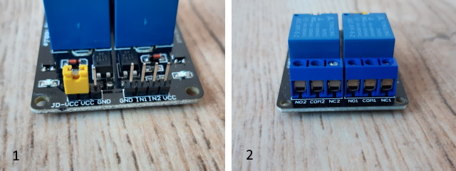
Figure 1 shows the connection to the Arduino board: the four-pin connector on the right. The first pin from the left should be connected to GND and the last one to Vcc. The intermediate pins, IN1, IN2 ... are one to each relay, in the same order in which the relays are located on the board.
Figure 2 shows the relay output, where you have to connect the 12 V cables from the power supply and the wires to the motors. A relay is an electronic switch. In this case, the centre connector (COMn) can connect to the right output (NCn) or the left one (NOn), where n is the number of the relay. When the relay is off, COMn connects to NCn. When the Arduino board activates the relay, COMn connects with NOn. Therefore, you have to connect a 12 V cable from the power supply to the central connector of the first relay on the board and, from this point, connect all the central connectors of all the relays with small cable segments. You have to connect the wires to the motors of each relay in the corresponding NOn output. I recommend covering with tin the tips of the cables using a tin soldering iron so that they don't fray and it is easier to connect them. 99% of assembly failures are due to loose or wrong connected cables.
According to the terminology explained in the previous article that I use in the robot control software, the Arduino pins correspond to the striking limbs in the following order:
SR: pin 22; HCR: pin 24; RR: pin 26; MCR: pin 28; LCR: pin 30; LR: pin 32; LL: pin 34; LCL: pin 36; MCL: pin 38; RL: pin 40; HCL: pin 42; SL: pin 44.
It is a good idea to also place them in this order on the junction box's outer terminal strip. In this way, half of the strip is for the right tower, and the other half is for the left one.
Since we are with the robot's electronics, I will show you a tool to facilitate the training. It is a flashing device that warns us an instant before the blow to help us react. Take into account that the device is entirely still and, suddenly, hits with one of the arms or legs. With circular punches, we can see the movement and react because the arc is relatively long, but with straight punches and kicks, it is hard to react in time. Usually, you won't use all the limbs at the same time (for instance, straight and circular arms to hit in the face are difficult to place at once), I take advantage of the free connectors to connect these small devices, which are as shown in this picture:
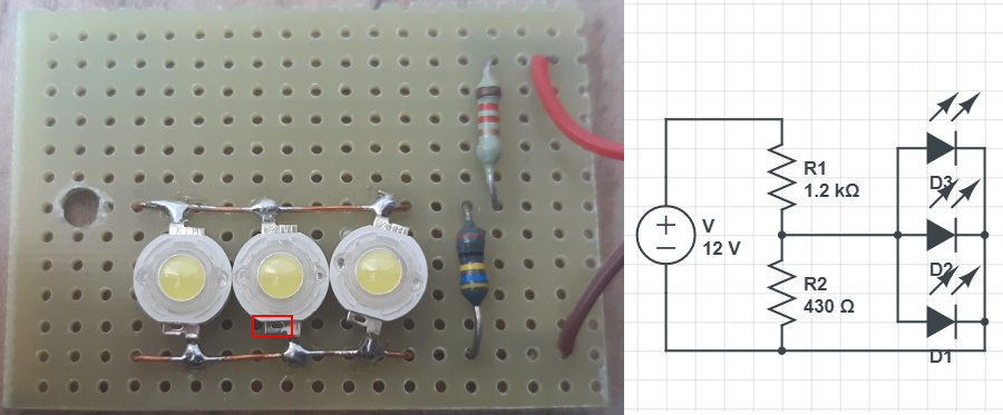
On the right, you have a diagram of the circuit. It consists of 3 high-luminosity LEDs and two 1K2 and 430 Ohm resistors, used to convert the 12 V supply into the 3.3 V required by the LEDs. I have signalled with a red box a mark in these LEDs. You have to connect the ground on this side. You can use a piece of prototype board to make these little devices. Put them near the arm for which you want the warning and use the software to turn them on for an instant just before the blow. You can program the time that they must be on and the delay until the arm hits.
With this, I finish the robot assembly section. In the next article, I will show how to use the software to control the robot and design the training routines.
Until next time, thanks for reading!


