Training sparring robot I
I will show in this series of articles how to build a self-defence and martial arts training robot. I have named Octopussy to the invention since you can put several limbs to simulate different types of punches and kicks directed to all of the body parts. It is controlled by a computer, an Arduino board, and an application, which you can download using this link. I also provide the application source code for you to make modifications as you want. It is written in C# with Visual Studio 2017.
With this robot, you can train your speed, attention, and reflexes, the same as with the punching-bag you can train your technique and strength. Throughout the article, I will explain how to build the different components. Also, I will put some links so that you can get all the relevant pieces. You can easily dismount the appliance to store it after use if you do not have enough space to have always it mounted. In this video, you can see a demo of how it works (if you can't see the video, here is a link to YouTube):
The robot structure
The robot's structure consists of two rigid PVC tubes of 5 cm in diameter and 2 meters high. You will also need an additional short piece of pipe for each of the limbs. You can purchase the PVC pipes at plumbing supply stores; they usually are 5 meters long, but you can ask to have them cut in the store to the desired size. It is also possible to buy shorter tube pieces separately since the excess 1 meter may not be enough.
The 2 meter high tubes will be placed vertically to hold the left and right limbs, more or less at a distance equal to the distance between your shoulders. For the structure to be stable, you have to build a solid base for each of the pipes. I have used a 60 x 40 x 2 cm plastic cutting board, which I have cut into two 30 cm wide halves. Under the boards, I have glued some rubber plates so that they do not move when hitting. I have added a 10 kg dumbbell disk to increase the base's weight:
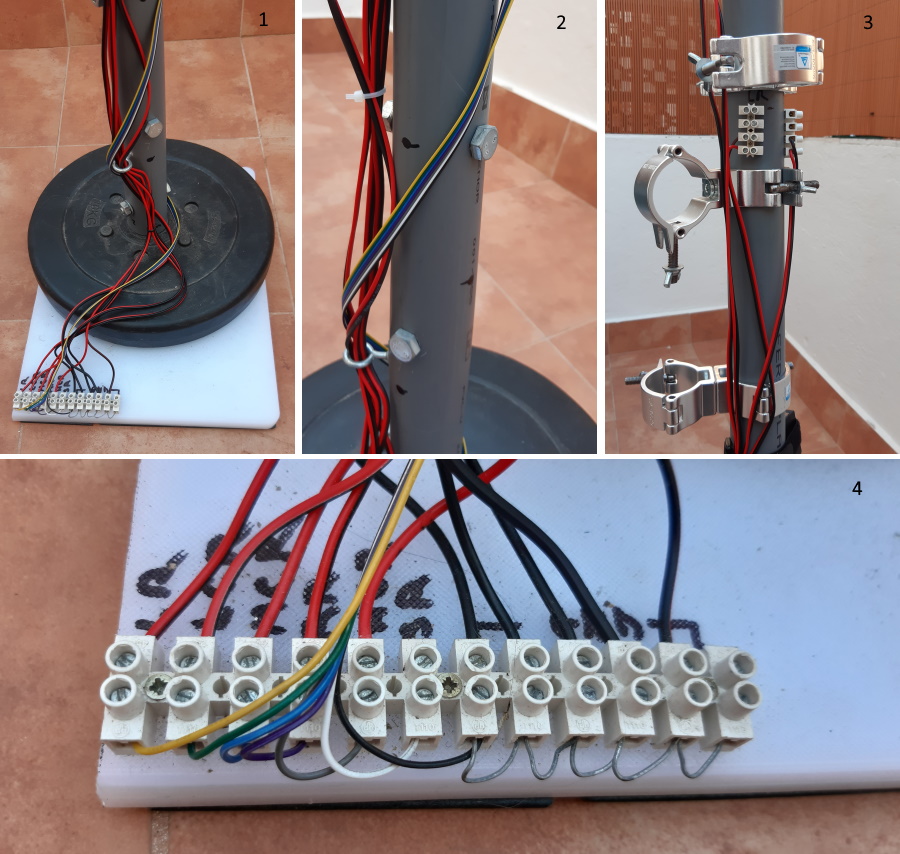
I have screwed a 12 connection strip for the electrical cables in each base, as you can see in figure 4. Six of these connections are for the motors' 12 V power supply; the other six connections are for the ground. You can see in figure 1 the cables for the motors, in red and black colour, that go up the PVC tube to each of the motor connections. I have placed another terminal connection strip at the appropriate height for each motor to be easily connected and disconnected, as shown in figure 3. I have put strips with four connectors, but two connectors would be enough, one for the 12 V and another for the ground. As I will explain later, you can also see in figure 3 the clamps used to hold the motors and arms.
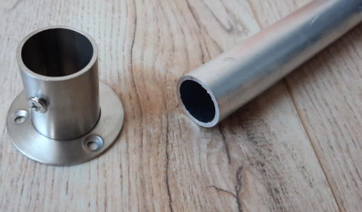
I have used a closet wardrobe rod holder and a 25 mm diameter aluminium tube to fix the pipe to the base, which is screwed to the board and inserted into the PVC tube. You can see in figure 2 the screws that go through the two tubes to hold one to the other. The wardrobe rod support has a screw to hold the aluminium bar, in which you have to make a small hole to fix it well with this screw:
The six limb limit per side is arbitrary. I have chosen this number because I consider that it is sufficient for all hitting combinations. In the following image, you can see more or less at what height I have placed the different connections:
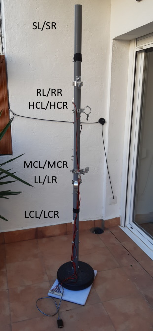
These are the different hitting points. The letters L and R refer to the left and right sides, respectively:
- SL/SR: this is an up-down strike like that of a stick.
- RL/RR: straight punches, such as a direct or a jab. I place them at the face level, but you can also put them on any other connector.
- HCL/HCR: high circular hit at the head level.
- MCL/MCR: medium circular hit at the waist level.
- LL/LR: kicks.
- LCL/LCR: low circular hit, aimed at the legs.
You can also see in the image the connection cable of the side tower with the power source that controls the motors. This cable is connected to the connector strip at the base. You can hold this cable to the PVC tube using a Velcro strip when dismounting the device. Loose wires are very annoying.
I have used a pull-up bar, which has the ideal width, to fasten the whole structure:
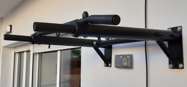
I use Velcro fastening cable straps to attach the PVC tubes to the pull-up bar, as you can see in figure 1. They provide a solid grip and are easy to remove:
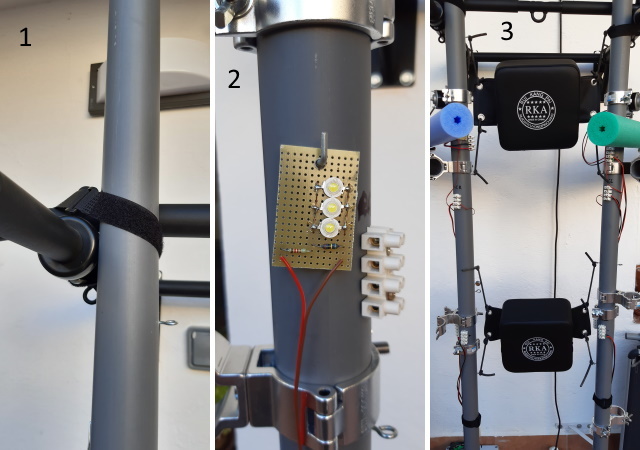
You can easily screw fasteners in the PVC tubes to place accessories, such as the device in figure 2, which I will explain in the next article. This device is to have a visual stimulus that gives some clue of where the hit will come from. The robot is utterly still until it hits; we need something that simulates the opponent's movement, or we will not react quickly enough. You can see in figure 3 some punching pads for you to hit the robot too. The punching pads are held to the side tubes with slingshot rubber bands for the blows to be well absorbed and the device does not move.
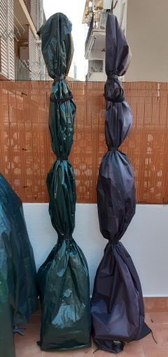
You can easily store these side towers in a small space, using patio umbrella covers to protect them. Don't forget to fasten them to the wall, or the wind will throw them on the ground. I use Velcro strips, which are easy to put on and take off:
Making the limbs
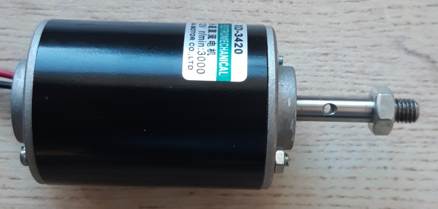
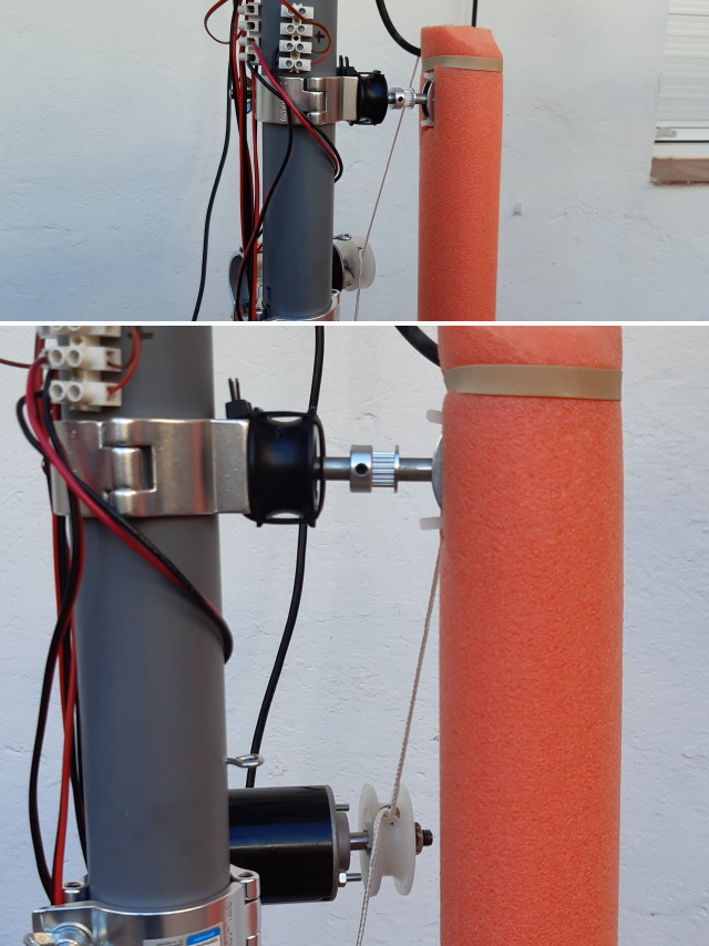
You need two elements to make each of the hitting limbs: an arm and an electric motor. The engine model that I have chosen has several advantages: it is a 5 cm diameter cylinder, so you can hold it using clamps of the same calibre as for the tubes. It also has a thread at the end of the axis that allows you to use a nut to hold a pulley and a hole in the axis to fix the pulley so that it does not slip when rotating. They are 12 V motors, just like the power supply I use:
You have to add a pulley to the motor to connect it to the arm and move it:
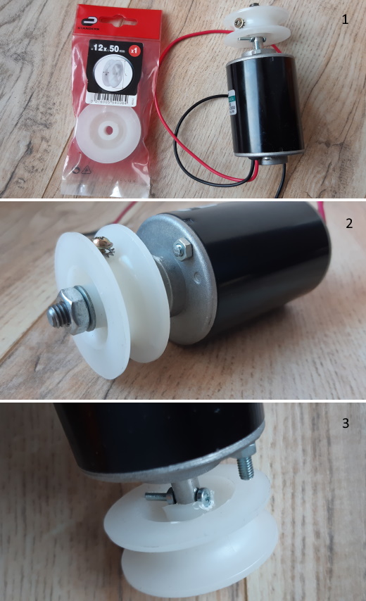
These pulleys have been hard to find. They are from Leroy Merlin, although anyone of similar size will do. The axis hole should be 8 mm in diameter; if it is smaller, you have to enlarge it with a drill bit. As you can see in figure 2, I have added a screw with a tooth lock washer to hold the arms' connecting rope. You can also see in figure 3 a way to block the pulley with a screw so that it does not slip.
I use 50 mm gauge lighting clamps to fasten the motors and arms to the PVC pipes. Two clamps have to be attached using a screw and a nut. You can hold items with them to the side pipes at any angle:
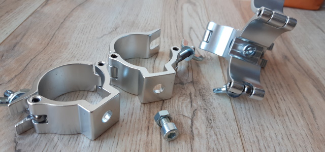
Although there are double clamp models, it is better to buy single ones. The double clamps have the nut welded to one of the clamps, and the other rotates freely, so they do not work to hold the parts unless you block the rotation. The screw used to join the two clamps should not be more than 3 cm in length, and it is better to tighten them using an Allen key. The motors must be held with care, as they can deform if you tighten them too hard and drop down if you tighten them too little.
Circular blows
The circular blows simulate legs, sticks, or arms, and, as the name suggests, they move in a semicircle around an axis. They consist of a motor and an arm. I have used pool noodles for the arms, since they weigh very little, and you can easily cut them to the desired size. The weight is important, as the motors could not move too heavy arms quickly. This material also allows you to shape the arm to simulate different types of circular blows.
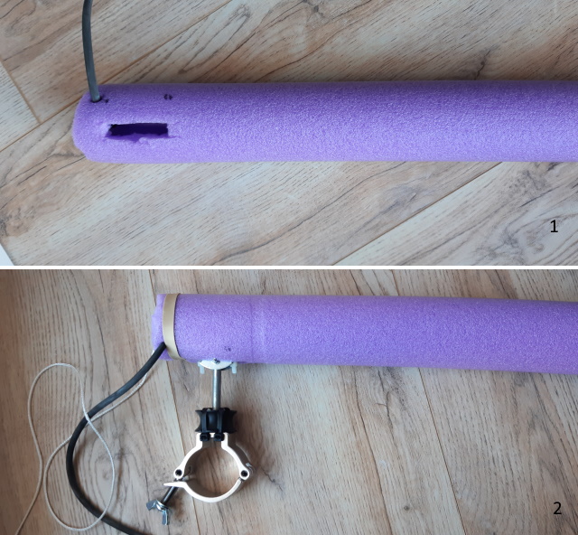
You can see in figure 1 one of these arms with a cutting to introduce the rotation axis, as shown in figure 2. You can also see a piece of slingshot rubber held inside the arm with a simple knot. This rubber piece is attached to the side PVC tube so that the arm returns to its initial position after striking. Since the arm is very light, the rubber does not have to be very tense, which could make the stroke too slow. The rope that sticks out in figure 2 is attached to the motor pulley to move the arm, as we will see later.
To build the axis of rotation, you will need a clamp, a pulley to hold the axis, a semi-threaded bolt as the axis, a short bar to hold the arm horizontally from the inside, and a couple of pieces to hold the bar:
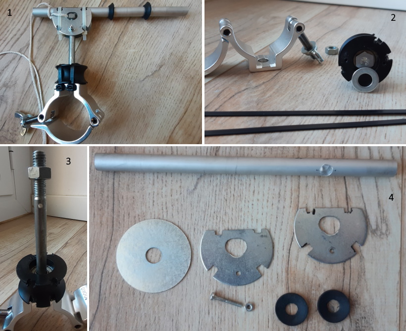
You can see in figure 4 the bar of about 20 cm long that will be the arm's skeleton. I have used a 20 cm aluminium bar because it is light, easy to work with, and resistant, but you can use another material. It has a hole to insert the end of the axis. This hole does not have to go all the way through the bar. I have used an 8 mm drill bit because this is the diameter of the axis bolt. The pieces that hold the bar on the sides are made from 5 cm washers. I have cut the washers with a hacksaw and drilled them to fasten them with a screw. I have filed four grooves to attach them to the bar with zip ties. The rubber washers are optional. In my case, I use them to adjust the aluminium bar to the inside diameter of the arm. You can see in figure 2 the bolt inserted in the supporting pulley. The little steel washer provides a solid turning base, for the clamp is made of aluminium, and it could be scratched and hinder the rotation. You may need to file the head of the bolt so that it rotates without friction.
You can see in figure 3 the bolt and the pulley from another perspective. The bolt is 10 cm long and 8 mm in diameter. I had to make a hole with a steel drill bit of about 3 mm, to hold the side pieces through it. Drilling steel is not easy, so if you don't know how to do it or don't have a suitable drill, you will have to turn to a handyman friend or acquaintance. The pulley grooves are to fix the pulley to the clamp with zip ties so it will not move; this is the simplest option I have found. You can see in figure 1 the axis wholly assembled, with the connection rope to the motor. The bolt nut is to provide a support base for the aluminium bar.
In the following image, you have an example of how to mount a horizontal arm using a PVC tube as a base:
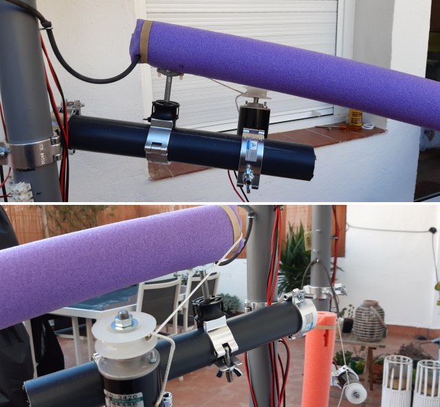
You will need five clamps for this assembly: two for the motor, one for the arm, and another two to hold all of it to the side tube. If you wonder why not use the engine itself as an axis, the answer is that this is due to inertia. The motor will rotate very slowly (this is due to the arm's length, not to its weight). With this system, the motor drags the arm instead of rotating it, using the lever law, and the blow has enough speed — physics stuff.
The vertical circular limbs, such as kicks or sticks, are mounted the same, but no additional tube is necessary, as they can be attached directly to the side tube:
Ignore the sprocket on the axis; it is a failed experiment that I was lazy to remove. In principle, the direction of rotation of the motor is indifferent. Still, if you want it to rotate in the opposite direction, you just have to connect the cables on the contrary.
Straight blows
The straight blows are most difficult to build, although, for me, they are the most interesting. Here, the motor must drag the arm a greater length, so you will have to mount it on a horizontal slide. I have used 40 cm drawer slides mounted on a PVC tube of the appropriate size, in my case, about 50 cm.
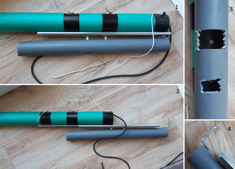
You can see in figure 1 the complete assembly. The drawer slide is held to the tube using two screws. It is essential to leave enough space so that the guide does not collide with the clamp placed at the tube's beginning. Always put the wing nut at the bottom of the pipe. You can see in figure 2 the extended arm. The holes in the tube shown in figure 3 are for tightening the clamping screws, and the stop in figure 4 prevents the guide from coming out when the arm comes back. If you buy the slides that I indicate in the link, you will have to carefully remove the plastic piece shown in the following image because it slows it. If the drawer slide disassembles, it isn't easy to reassemble it:
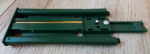
The black strips on the arm are made with duct tape to reinforce the attachment points to the drawer slide:
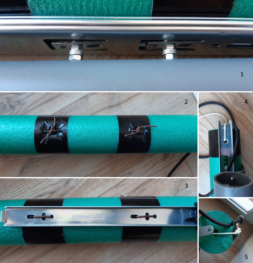
You can see in figure 1 the detail of the fastening screws, with washers and nuts that act as spacers. You have to use screws with the flattest possible head to not rub against the slide. The head of the screw must be inside the slide. Hold the screws to the tube with a nut.
The arm is sewn to the slide's upper segment, which is the one that extends further, as indicated in figures 2 and 3. I have used pieces of cable because the ropes I used at first ended up being cut. They must remain tight underneath so that they do not rub and impede the slide's smooth movement. You may also lubricate the slide with lubricating oil from time to time, better if it is silicone oil, which does not damage the plastic parts.
The rope connecting the motor is on the back of the arm, holding the arm, as indicated in figures 4 and 5. There is also a slingshot rubber band to move back the arm after the blow.
In the following, image you can see how to hold these arms:
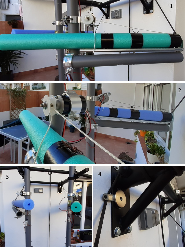
You can see the connection with the motor in figures 1 and 2. The motor pulley should be located more or less in the centre of the arm, for the rope does not come off. The arms have to be placed with enough lateral inclination so that the blows go to the face. You can see in figure 4 the solution that I have used to fasten the slingshot rubber band to the wall, putting a strong neodymium magnet in the pull-up bar. You can also set a nail on the wall, but I prefer not to make unnecessary holes.
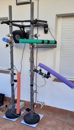
To finish, here is an image with a complete assembly with four limbs. In the next article, I will explain how to assemble the electronics of the robot:
That's all for now, thanks for reading!


