ThiefWatcher, a homemade indoor surveillance system I
In this series of articles I will do a bit of DIY to build a video surveillance and alarm system against home thefts, using relatively cheap materials and a program that will notify to your mobile phone in case of detecting intruders and allow you to take photographs of them to be able to immediately notify the police and provide them those photos. Rapid identification of thieves can be crucial for you to recover all our possessions quickly.
This time the solution consists of quite many projects. In addition to the desktop application that works as a control center, I have used Xamarin to create a series of projects for the Android, iOS and Windows Phone App clients. I have also created a few projects that implement the different protocols used by the application, to control the cameras, call the mobile phone, detect the presence of intruders or store the photos in the cloud.
In this link you can download the source code of the ThiefWatcher solution, written in csharp using Visual Studio 2015.
The hardware
First, let's look at the hardware that I used to implement the whole mounting. This is the system schema:
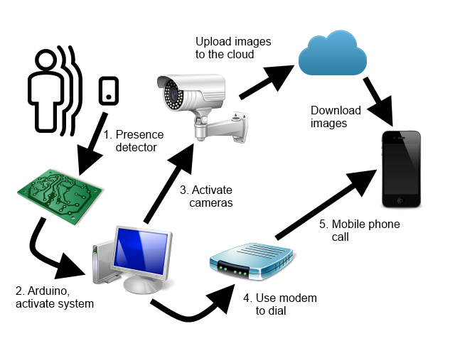
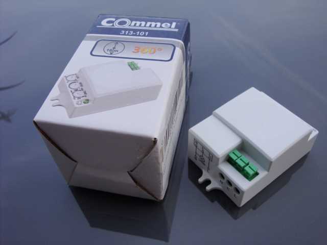
First, we have a presence detector switch, which will activate when it detects an intruder, it is like any other switch, just connect two cables from the power supply to the input and use its output to activate the device that will notify the event to the software to enter on surveillance mode.
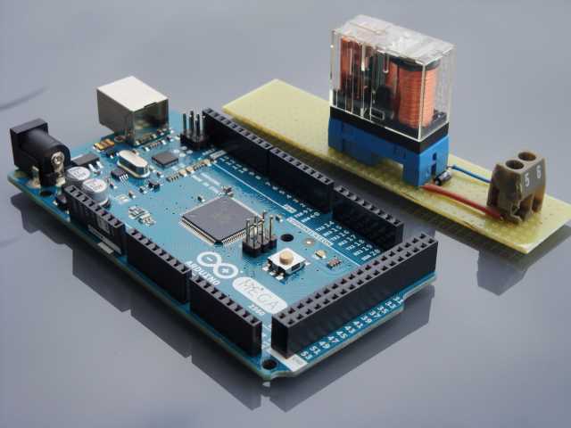
The device that I use to activate the system is a simple relay. The switch turns on a 12-volt power supply, which in turn activates the relay. When the relay is activated, it closes a circuit that connects an input of an Arduino board (in my case an Arduino Mega board) with the 5 volt supply of the same board, and it sends a signal through the USB serial port to the computer where it is installed the application that controls the entire system.
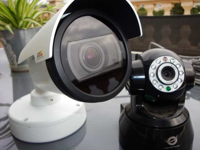
Once the activation signal is received, the system puts on the video cameras, which will start taking photos and upload them to the cloud or to the medium that you have configured in the system. The system does not work with a continuous video channel, since the upload of images with an ADSL connection to a service in the cloud can be quite slow. On the other hand, it is sufficient to have photographs of the intruders to be able to provide them to the police for identification, and they are more manageable than the videos.
As a cloud service I used Dropbox, which is free and very simple to use. The cameras are something else. In my case, I have two cameras, an IP camera with NetWave cgi protocol, which is relatively cheap, and an Axis camera with VAPIX CGI protocol, which is a professional one with very good performance, but with a fairly high price. Both cameras have the ability to take pictures in the dark.
The key to the system is that we be immediately informed that someone has entered our home, for which the simplest is to receive a call on the mobile phone. For this I have connected an AT modem to the computer and the telephone line and use AT commands to dial the number or numbers to notify.
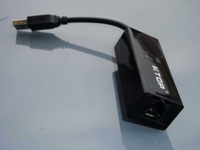
In addition to all this, in my case I have a UPS (uninterrupted power supply) in anticipation of power outages. There would be also the issue of a cut in the telephone line, which would also leave us without the internet connection, which can only be avoided using a 3G modem, although we would lose the possibility of calling the mobile with the telephone modem and we would have to implement another type of alarm protocol, For example via Skype. The system allows make any combination of protocols, as we will see later.
The ThiefWatcher application
As for the application that controls all this, ThiefWatcher, there are a series of protocols for each of the tasks in which the system processes are divided, and dependency injection is used to configure each one. These protocols are implemented through an interface, which is defined in the WatcherCommons class library, in the Interfaces namespace.
The different protocols defined are the following:
- IWatcherCamera: used to communicate with cameras. I have implemented this protocol for two camera types, NetWaveProtocol, for IP cameras that implement the NetWave cgi protocol, and VAPIXProtocol, for cameras that implement the VAPIX cgi protocol.
- ITrigger: used to trigger the surveillance system. I have implemented a simple signal through a serial port in the ArduinoSimpleTriggerInterProtocol class library.
- IAlarmaChannel: used to notify us that an alarm has occurred. I have implemented two libraries with this type of protocol, one that makes a phone call using an AT modem in the ATModemProtocol class library and the other to send a notification via Skype in the LyncProtocol class library.
- IStorageManager: used to send photos and control messages. I have implemented two versions of this protocol, one that uses Dropbox to exchange images and command and response files, DropBoxProtocol, and another that uses Azure blob storage for the same purpose, AzureBlobProtocol.
I will comment on all these protocols in the next article in the series. For now, let's see how to configure them in the ThiefWatcher application. One of the windows of the application is the control panel, which you can use to select and configure the protocols you are going to use. The appearance is as follows:
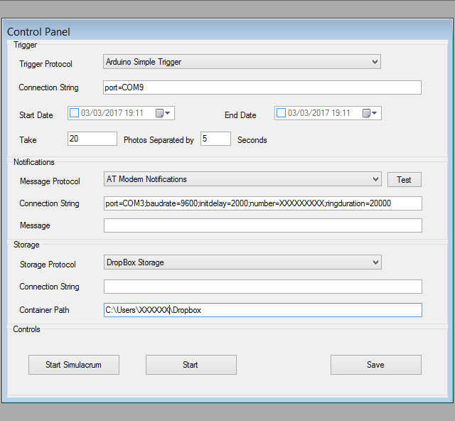
At the top of the panel, you can see the alarm configuration. A drop-down allows you to select the protocol. The connection string allows you to define all the parameters required for the configuration. These parameters will depend on the selected protocol. In the following article of the series I will explain the values for the protocols that I have implemented.
The start date is used to set the time when the system begins the surveillance process. Before this date / time the system will not send alarms. If you do not select a start date, the system will start monitoring from the moment you activate it.
The end date indicates when to stop the system and stop monitoring. If you do not select a date, it will never stop automatically and you will have to stop it manually.
We can tell the system to take a certain amount of photographs, separating each one a certain amount of seconds from the next. When the system is activated, the first picture will be taken.
The notifications section allows you to select the protocol that you want use to notify a possible problem. In addition to the configuration indicated in the connection string, you can set a default warning message, if the protocol supports this functionality. The Test button allows you to perform a test of the alarm protocol without having to perform a simulation.
The storage protocol is the one used for the transmission of images and commands and control responses, in addition to the connection string with the set up parameters, it allows define a relative path to store the data.
As for the control buttons, you can perform a simulacrum of the system, in order to test new protocols, for example. The difference between a simulacrum and the real operation of the system is that in a simulacrum the alarm protocol is not taken into account, and the system starts directly in a state similar to that produced after an alarm is triggered, but without taking photographs.
The real monitoring mode starts when you press the Start button, and with the Save button you can save the changes to the configuration.
To configure a new camera you have to use the File / New Camera... menu option. The program will first ask you to select the type of protocol used by the camera. Then the program will ask for the access data, which consists of the URL to access the camera, the username and password to connect. Then the following window will appear:
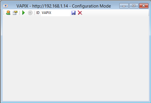
With the first button, starting from the left, you can change the access data to the camera. The second button will show a dialog box to configure the camera settings. Following you has two buttons to start capturing images and stop it. You have to write an identifier for the camera in the ID text box, and finally you have a button to save the camera settings and another to delete the camera from the configuration.
And that's all by now. In the next article we will review the details of the configuration of each of the protocols and the cameras.


